

This article gives an executive summary of the report on the future development of hyperloop infrastructure written by Delft Hyperloop. For the full report, click the button below!
Read the full report hereFor the implementation of a new infrastructure, there are numerous aspects that need to be considered. A new mode of transportation with its own new infrastructure requires advanced safety standards, possibly novel building technology, and different maintenance regulations and asset management. A safety assessment of the hyperloop system has been made by Delft Hyperloop, where a recommendation is made of the first publicly shared concept for the hyperloop safety system (Delft Hyperloop IV, 2020). With this report, Delft Hyperloop VI presents research into the two most distinctive parts of the hyperloop infrastructure. First, research is done into the best material to use for the large network of tubes and the hyperloop pods that speed through them. For the most efficient active infrastructure, research is done into the energy management of the hyperloop system, to map out the consumption of all the different parts and give recommendations on how to provide them with energy.
Introduction
If the electrical energy consumed by the hyperloop system is supplied through sustainable sources, the hyperloop can operate emission-free. Sustainability is therefore often named as one of the hyperloop’s biggest advantages over its competitors, such as aviation and high-speed rail. However, to make the hyperloop actually sustainable, careful design choices for hyperloop infrastructure have to be made. Two of the largest components of the hyperloop, the materials used in the infrastructure and its energy management, need to be carefully thought-out. The materials used, must meet all the requirements for hyperloop operation, but must ideally also be sustainably manufactured and durable. Good energy management is crucial to make sure that every component in the hyperloop infrastructure is supplied with green energy and thus operates emission-free. This report aims to make recommendations on what materials should be used for hyperloop tubes and pods and to formulate a good energy management strategy by calculating the energy and power consumption of major hyperloop subsystems and evaluating how these subsystems can be supplied with green energy.
Tube Materials and Structure
As hyperloop tubes will cover thousands of kilometers in an international hyperloop network, the impact on its surroundings will be considerable. It is therefore essential that the most ideal tube material is implemented in terms of structural properties, technical requirements, and wider criteria points. Four different materials and systems are analyzed on their suitability for the hyperloop tube: a steel tube, a steel reinforced concrete tube, a carbon-fiber reinforced concrete tube, and a steel tube with wooden support beams. A structural analysis of a simplified model of the tube is performed in order to demonstrate how existing constructive norms can be applied on hyperloop tubes, to give insight into the order of magnitude of the applied loads on the structure and to offer the required dimensions of the tube. In the simplified structural model of a single tube segment of 30 m long with an inner tube diameter of 3.5 m, the following loads are taken into account: self-weight, dead load, wind load, and vehicle loads. The structural analysis checked the proposed materials and systems on their strength and stiffness, resulting in the following values for the variable tube dimensions.
For the steel, steel reinforced concrete and carbon-fiber reinforced concrete variants, the dimensions above offer sufficient strength and stiffness against the applied loads. The steel-wood variant meets the strength requirements, but is not stiff enough to prevent large deflections from occurring in the wooden support beams. In further technical requirements,
the performance of the variants regarding buckling, fatigue and airtightness is covered. Lastly, in the wider criteria, the materials are examined on material costs, production, durability (where thermal expansion is discussed as well) and circularity. Overall, the steel variant has an excellent strength/weight ratio, allowing for slim constructions, is fully recyclable and is airtight. Buckling, chemical interactions and its rather high price form potential issues for this variant.
The steel reinforced concrete variant requires much larger tube dimensions and is less circular, yet it is the most low priced option and has simple and flexible manufacturing methods. The carbon-fiber reinforced concrete variant is very durable and allows rather slim dimensions. Yet, the addition of carbon fiber also makes this variant more expensive and less circular. The steel-wood variant did not pass the structural analysis but could find benefits in its circular nature and simple production process
Choosing the Pod Material
To give a recommendation on the best material to use for the hyperloop pod’s skin and structure, referred to as the shell, first, the mechanical environment of the pod is analysed for all operations. This analysis is based on a general concept of the hyperloop pod and not on a particular design, since concrete and elaborate designs are sparsely found in literature. From the forces that work on the pod during operation, the severest come from the vacuum exerting a pressure difference, and inertia force from emergency braking. Extreme temperatures of close to 100◦C in which the pod operates can be caused by heat radiation from the tube. From the system analysis, six requirements are established for the shell of a general hyperloop pod:
R-1: The pod shell must accommodate for loads of the order of magnitude of 115 kPa;
R-2: The pod shell material shall have a high damage tolerance;
R-3: The pod shell material shall fatigue resistant;
R-4: The pod shell material shall operate normally in the temperature range -60◦C – 100◦C (213 K – 373 K);
R-5: The pod shell material shall be airtight;
R-6: The pod shell material shall not have deteriorated properties due to outgassing and/or offgassing.
Seven materials are selected as potential pod shell material. These are carbon fiber, Kevlar 49 thermoplastic composite, hemp fiber composite, Al-Cu-Mg alloy 2024-T3, Al-Li alloy 2060-T8, GLARE and high strength steel. These materials are then assessed on the following criteria:
- Workability and Production Process
- Costs
- Durability
- Recyclability
- Weight
A trade-off in this multiple criteria analysis on the selected materials results in high strength steel being the best suitable material for the shell of the hyperloop pod. This recommendation is based on the general concept of the hyperloop. It is important to note that a different outcome of an assessment, that is based on a concrete design, is not ruled out.
Energy Consumption of a Hyperloop System
In order to see how major hyperloop subsystems can be supplied with sustainable energy, first, the energy and power consumption of these subsystems have to be estimated. These consumption numbers depend on system characteristics, like the technology used for the propulsion, levitation and safety systems of the pod and operational characteristics. By setting requirements and criteria for the different subsystems, the best option for these are chosen. For the propulsion system, an LSM-booster system is chosen for its energy efficiency. For the levitation system, an H-EMS system is chosen for compatibility with high-speed lane switching technology. For the safety systems, safety wheels or an LIM could be used. By using estimations from literature, comparisons with similar existing systems and own calculations, the energy and power consumption of the vacuum pump system, propulsion system, levitation system, safety system and other on-pod systems can be estimated. To make the results more tangible, results for the daily energy and power consumption of a hyperloop corridor between Amsterdam and Paris are given.
The total daily energy consumption for the route Amsterdam-Paris is found to be 1152 MWh (420 GWh per year) when operating on full capacity during 16 hours of operational times (06:00 – 22:00). One of the main contributors to the energy consumption are the vacuum pumps with 516 MWh per day in case the tube has to be completely depressurized 2× per week. While the compensation of leakages is only 2 MWh per day, a complete depressurization of the tube in 24 hours consumes 1.8 GWh. The other major contributor to the total energy consumption is the propulsion system, with a daily consumption of 634 MWh. The power of the propulsion system is delivered in pulses over the LSM-booster stations. Due to that pulse shaped consumption curve, the power of the propulsion can also reach high values with a peak power of 100 MW in case several pods pass by booster stations simultaneously.
The on-pod systems are responsible for an energy consumption of 1.48 MWh per day, with a peak power consumption of 230 kW. This mainly comes from passenger comfort systems, the H-EMS levitation system as well as safety systems. While the energy of the on-pod systems is comparably low, the challenge is the provision of energy to these systems, since they are dynamic and can therefore not be connected to a static energy source, unlike the vacuum pumps and the propulsion system.
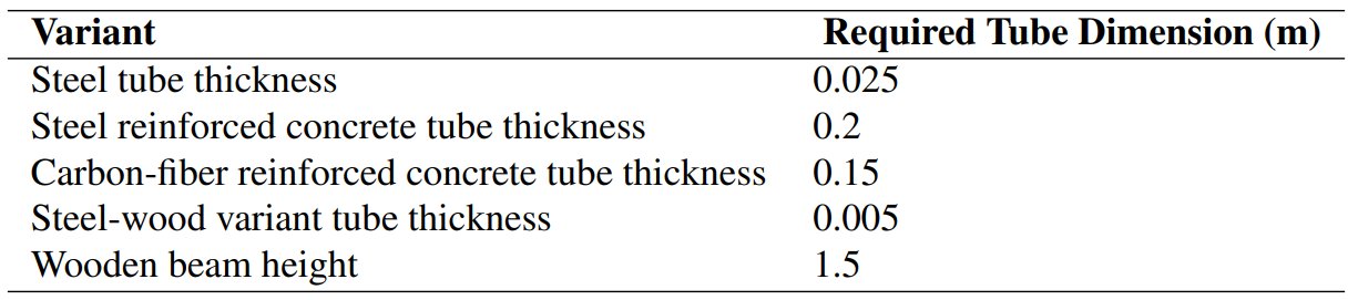
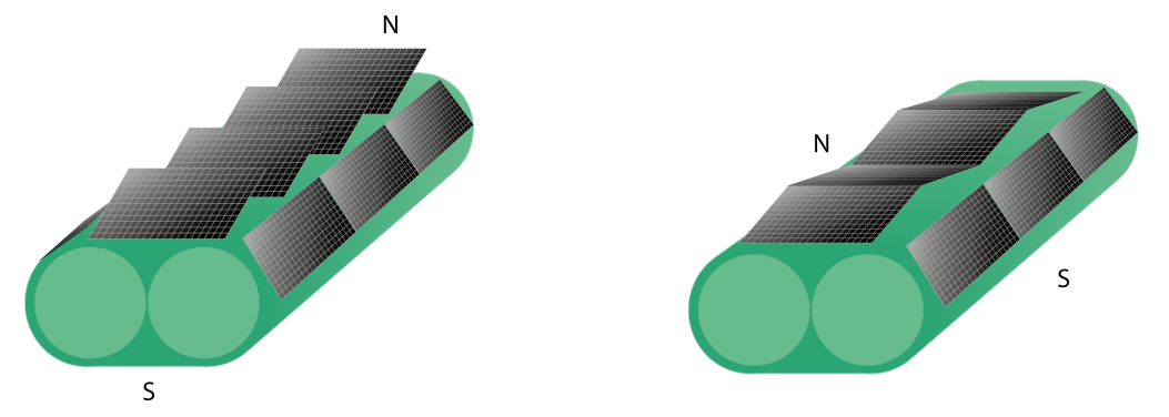
Energy Sources for the Hyperloop System
Even though the hyperloop is much more energy efficient when compared to other modes of transportation, still, a lot of energy is needed to operate a route or even an entire network. To be able to implement and operate a hyperloop, the sources of energy need to be specified. As the hyperloop is intended to not only be efficient, but also overall sustainable, renewable energy sources are investigated. Solar energy (photovoltaic cells) is an interesting candidate, as no additional land is used for this energy source. The solar panels can be mounted on top of the hyperloop tubes. The produced energy depends on different factors, such as the usable area for placing solar cells, the solar irradiation, and the location and orientation of the Amsterdam-Paris route. Considering these factors, the setup of photovoltaic cells is evaluated. A mix of south-oriented and east/west-oriented setups is used to have both a high total production, as well as an evenly distributed generation curve. Several suitable cell technologies for the implementation in roughly 2035 are analyzed, such that the total energy produced can be calculated. High efficient photovoltaic (multi-junction monocrystaline silicon) cells are the most likely technology to be used to cover the top of the tubes, stations and other infrastructure. They have a nominal power of roughly 300 W/m2. As a European average, an energy production by solar panels of roughly 60 GWh/100 km per year can be assumed. This is slightly higher than the route Amsterdam-Paris, with 44 GWh/100 km (total 220 GWh) in a year.
For most average European routes, the energy production does not exceed or even fit the energy consumption of the hyperloop system. This means that additional sources are needed. They can come from any renewable source that is suitable in the specific place. The choice of the additional source depends mainly on external effects such as the location and availability. Additional sources could include:
- External solar parks
- Onshore- and Offhshore wind parks
- Biomass
- Geothermal energy
- Hydropower
While renewable sources can provide the amount of the energy needed for the hyperloop infrastructure, the energy generation, especially from solar energy, has fluctuations over time (seasonal changes and day/night-cycles), which are not identical with the consumption curve. These challenges can only be overcome by integrating a distribution system to the infrastructure to bring the consumption- and production-curve together.
Energy Distribtion to the Hyperloop Subsystems
When using renewable energy sources, some sort of energy storage or energy distribution system is needed as the energy and power production cannot cover the energy and power consumption at all time. Energy storage and other forms of distribution (over time and space) are thus needed.
For the static subsystems, connected distribution systems, namely a connection to the power grid as well as local energy storage systems (ESS) are investigated. These systems need to be able to compensate different kinds of fluctuations:
- Peak shaving (in the range of seconds)
- Day/Night-cycle (in the range of hours)
- Fluctuations due to weather (in the range of days)
- Seasonal changes (in the range of months)
Therefore, a mix of different ESS in combination with a power grid connection is expected to be the most suitable solution. For peak shaving, flywheels are a promising option. In the medium time range, thus from hours to days, batteries and hydrogen are the most promising for storage solutions. The system chosen finally depends strongly on the innovation and development in ESS in the upcoming 15 years. Options such as Superconducting Magnetic Energy Storage (SMES) for peak shaving for example seem very promising, but this technology is currently not ready for such an application.
The storage over long times depends strongly on external effects and the production curve, which is very different depending on the location of the route. As a consequence, the ESS most suitable are strongly location dependent and a general solution applicable for any European route cannot be chosen. Options for long-term storage could include pumped hydro or compressed air (CAES) depending on the given situation.
A good solution to compensate the seasonal fluctuations would also be a connection to the power grid, which acts as a distribution network and can provide energy from another source if the internal sources do not produce enough. A hyperloop system without a connection to the power grid is therefore unlikely. The same also holds for a system only depending on the grid and not including any ESS at all.
For the dynamic subsystems (on-pod storage), batteries and hydrogen (in combination with fuel cells) are the two most promising ESS. While there is no significant advantage for any in size, a hydrogen system does have a clear advantage in weight as it is much lighter (202.5 kg versus 522-631 kg for batteries). Fuel cells also have a longer life expectancy compared to batteries. Another upside of hydrogen is that refueling takes only three minutes. Compared to the 15 minutes that batteries need when fast charging, this shorter time means the operation can be optimized. However, batteries have a significant advantage over a hydrogen system in terms efficiency. While batteries have an efficiency of around 90%, a hydrogen system has an efficiency of roughly 50% round (with a fuel cell efficiency of 60% and electrolysis efficiency of 80%). This efficiency advantage makes batteries the best choice for an energy efficient on-pod system.
With technological advancements in all ESS field discussed in this report, it should be noted that the most suited options for hyperloop subsystem applications can change over time. With the time to the implementation of the hyperloop still unknown, some ESS might become more suitable over the next years.
No responses yet